


In my previous post I described the lead-up to my shipbuilding project, the USS Midway in 1/800 scale. This time we’ll get into the nitty-gritty of the project.
So, as mentioned, my starting point was to use an Arii 1/800-scale model kit. And also as mentioned, I soon discovered a few issues and challenges. Not surprising when your target is in constant motion. My original goal was to build the model in the post-1986 configuration, but the kit is much closer to 1971. Once I figured that out, it became a matter of ferreting out which features were added, changed, or removed– and when. Oh, and there’s that other minor matter: I had to decide when enough was enough. Just how picky did I want to get with the accuracy?
For the first, the ferreting of features, I figured that photos were far and away the finest and fastest way to find diFFerences (couldn’t think of any synonyms that started with F, sorry). But it turns out that there are official US Navy drawings on the interwebs that shows the whole 1986 project in fine detail. Just a simple matter of comparing photos and drawings to the out-of-the-box model, right? Well, sorta. I’ll explain in a bit. But that’s the basic idea.
For the second, deciding on the level of accuracy and detail, that’s driven by the following factors:
- Difficulty, i.e. just how many lifetimes would it take to execute the change? Did I want to widen the hull? Did I want to get every single bump on every single catwalk correct?
- Cost. Do I want to buy frets of aftermarket brass railings, additional aircraft and such?
- Size. How fine can you model with styrene in 1/800?
I have lots of styrene structural shapes and in varying thickness of sheet material, so I felt confident I could fabricate most things I needed to do.

Basically, I ended up deciding to focus on the island modifications. There are major things going on there, as compared with the as-built version– and the 1971 version is not all that different from the 1945 appearance, really. I also decided to do a few things with the weapons on the sponsons, as mentioned in the previous post.
So: a simple matter of determining the conversion factor between the drawings and the model so I could build the add-ons, right? WRONG. I carefully calculated the ratio and measured out parts, painstakingly assembled them to the island, and… and… they just looked wrong. Something wrong with my arithmetic? I started measuring stuff again. Then I’d measure in a different place. Then I’d reference the empirical measurements on the blueprint. Nothing added up. So I started measuring different dimensions on the model and comparing to the blueprint, calculating the scale. And, guess what? Depending on the measurement, I got scales ranging between about 1/710 through 1/790. Um, that’s a 10% variance in some cases! Guess what, people? This model is far from being a 1/800 model, or really any scale at all! Basically it’s too tall for its length. And that’s being generous in a generalized way. If one were to draw a line down the middle of the points on the graph, best guess is somewhere around 1/755 in average, give or take.
Well, heck.
What this means is: basically build stuff so it looks more-or-less right, and adjust it so that it fits in the available space.
If that’s not enough to make you throw your hard-won eBay prize in the ashcan, we’ll keep going. Actually knowing that took some of the pressure off, because one of the things I do best is carving and filing. Okay, that’s two things.
Here’s what you need to add to the island structure, taking the large view:
- The radar room and platform (as originally built), on the starboard side of the funnel. (There’s one included in the kit, but it’s not right.)
- The comms room just ahead of this.
- The upper comms room that sits on the island just forward of the funnel.
- The radar room / deckhouse structure aft of the island, including its legs and cross-bracing.
- The radar tower itself (bwahahaha!)
And one other thing: if you think I’m giving you all the dimensions, think again. Download the drawing and go through the agony yourself! You’re no better than me.
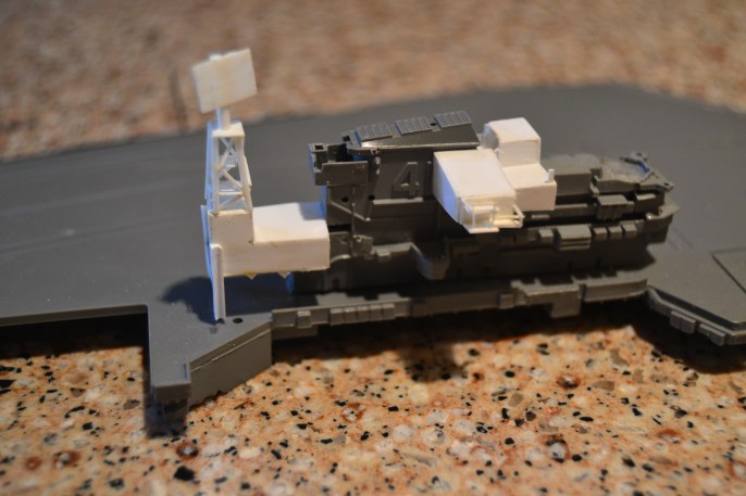
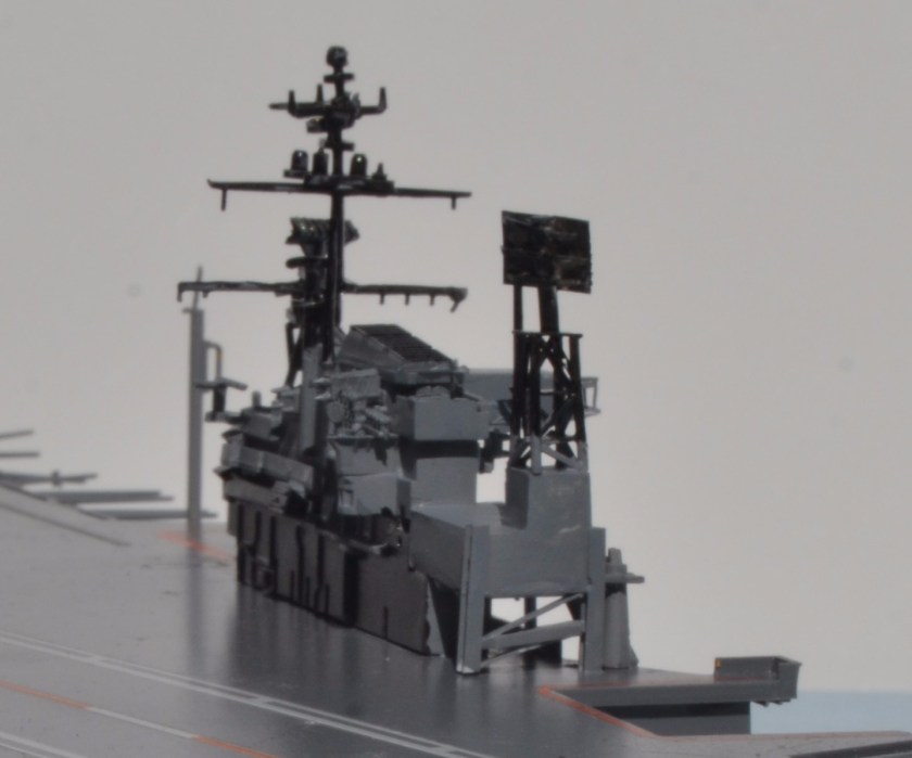
So, refer to the photos above and below. The white stuff is the stuff I added.


Here’s where I will stop and point out the one single thing I’m most unhappy about: those two projecting comms rooms on the starboard side of the island. They’re definitely oversize, especially the aft room. I couldn’t decide whether it was enough of an overage to cut them off and start over, and eventually decided just to keep them. Oh well. Once all the other details are added to the superstructure, they’re lost in the clutter somewhat anyway, or at least that’s what I tell myself.
I originally started to rough-in some railings, using trimmings from .010 styrene, but I jumped the gun. Should have done all of that last. A lot of them got knocked off with handling. If you want to spend a couple dozen dollars you can get brass railing material in 1/800; I didn’t bother. It’s that choice we all have to make about what is good enough for us.
So here’s a few comments about the construction. I used sheet .020 styrene for all the flat surfaces, which is a great material because you can cut it with scissors. The legs under the radar house are H-column trimmed to fit. The radar tower (a challenging sub-assembly) is four legs of thin styrene rod, I believe 1/16″. Crossmembers are HO-scale 2X2, which is .022 X .022″. The three decks on the tower are .010″ styrene. The front-right deckhouse leg consists of two laminated strips of .020; the inboard piece extends flush to the deck whereas the outboard layer overlaps the deck edge. The radar antenna was scored with my Exacto in a crosshatch pattern to simulate the gridwork.
I added most of the stock details from the kit; a few are excluded due to later mods. For instance, after the guns were removed there was no need for a gun director and so it was also uninstalled. There is a section of starboard catwalk that must be trimmed off to make room for the passage at front right of the radar room/deckhouse. I replaced the radar on the mainmast with the one that would have gone on the lateral radar platform (trimmed slightly on each end to fit).

There are a couple of relocations that become necessary. First, the secondary (aft) mast does not get installed in its original location but is shifted to the left and is attached to the port wall of the Radio & ECM Room just forward of the funnel. Second, the main crane must be shifted outboard to clear the new superstructure elements. When I did this, I carefully trimmed off the mounting post and used it to fill the hole in the deck, then just cemented the crane to the new location. I strongly suspect that this was moved on the real ship in the 1966 rebuild as well. A truly great modeler would have taken the time to ream out the spaces in the crane girder, but I lean slightly to the impatient, lazy end of the spectrum (my family would disagree) and I did not go to that trouble.
Side note: my styrene cement of choice is methyl-ethyl ketone (MEK). Plastruct sells it in a bottle with a brush applicator, but I refill my bottle from a can that I bought at Ace Hardware at a fantastically-reduced price per ounce. Just be careful that you don’t overdo it or you can ruin delicate parts– and especially paint.
But First! (Don’t you hate it when you hear that?) Don’t attach the deck just yet. The kit comes with an option of installing the No. 2 (starboard side aft) aircraft elevator in the up or the down position. I decided to go with down, which meant having the hangar doors open (i.e. omit the kit part), which meant, having to install the hangar deck. I installed some supporting members and cut a piece of .040 styrene for the hangar deck. Since not much of it’s visible I only did a portion of it. This also means that you should prepare a couple of aircraft now so you can install them inside the elevator opening. At this point you want to skip ahead to the discussion of eras and the appropriate air groups for your chosen era. That discussion occurs in a future blog entry which hasn’t been written yet, so I suggest you either wait a bit, or become clairvoyant.
Now, back to the ship. There are a few other comments I need to make about the construction. The kit’s instructions have you install the deck-edge whip antennae at a rather early stage of the construction. If you want the ship rigged as if it is in port, then go ahead. If you want to show it in operation, read on. While at sea these antennae swivel out and are basically parallel to the ground… um, water. This is for obvious reasons. But the kit doesn’t mold them that way. So you must cut them and reattach the whips at a 90-degree orientation. This makes them more delicate (ask me how I know). If I had it to do over again, I’d just wait until nearly everything else is done before tackling that part of the assembly. I also had to replace three with pieces of .018 wire since they mysteriously vanished. The wire antennae looks so much better than the chunky plastic ones that I wish I had just replaced all of them! Oh well, maybe some other time.
And speaking of some other time, this blog post has become rather lengthy, so I will address the painting and finishing, and the aircraft complement, in a third installment. 

One comment